7th Septembre 2021 – Schéma de câblage ajouté
 A large and incredibly versatile Complex VCO – worth the work!
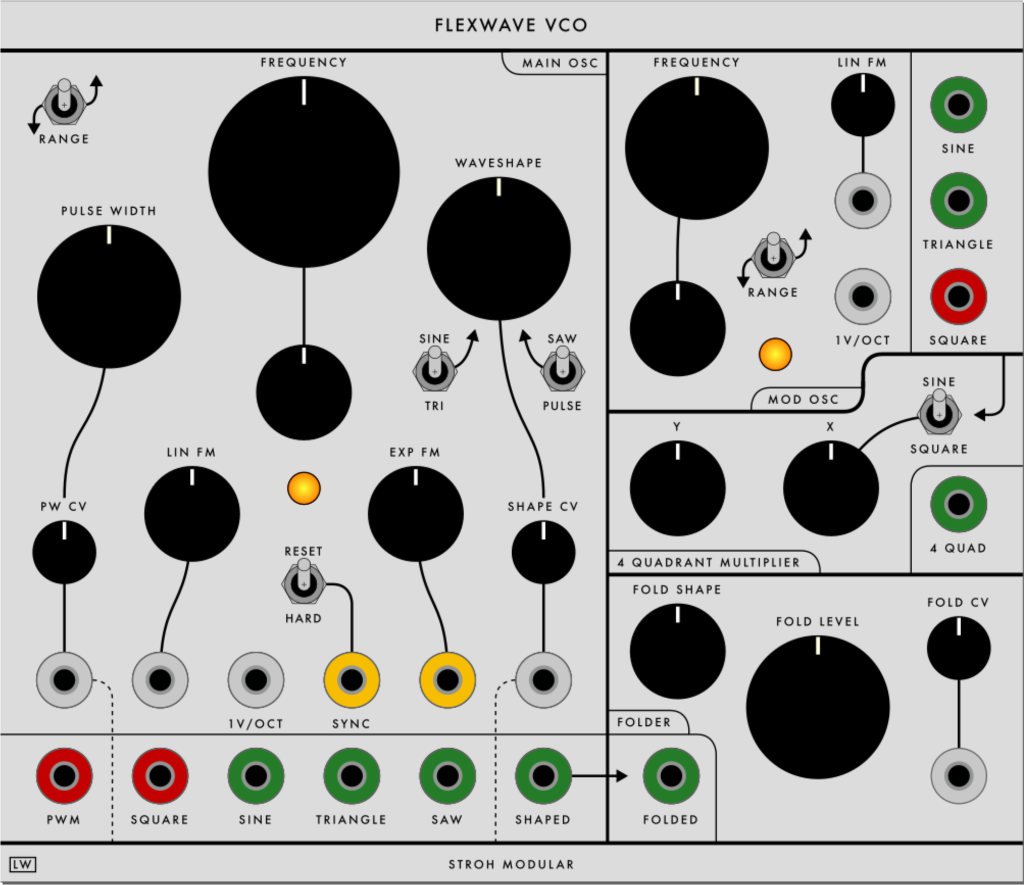
Above photo is panel in STS livery, I would use this for my own builds (LW colour scheme):
 (I would probably like to use cream knobs, but large ones can be a bit odd!) (Also I might use a violet jack for SYNC)
Stroh Flexwave VCO – PCB and panel set available from Synthcube:
Wiring Diagram:
I’ve tried to make it as simple as possible, bussing ground and the power rails on the panel etc. The pads are shown as on the PCB, text above or below boxes follows how the PCB is labelled and should match exactly. There may be errors. Some pads are not where you think they might be, the Sine output from the main VCO for example is on the longer side next to the FOLD CV pads for the Folder.
Colours are randomly chosen – so do think while you are working rather than attaching things that are the same colour that are not connected to lugs of pots etc.
Panel / pots etc shown from the back as usual…
NOTE: On the PCB there is a capacitor (C15) to AC couple the main osc Exp FM input, I have ignored this as I don’t think I would want AC coupling on this input, the diagram reflects that. LIN FM on both oscillators goes through a cap on the PCB – note main osc LINFM pad wiring, the leftmost pad as shown below is 0V, if you get confused look at PCB!
DOWNLOADABALEABLE PDF AT BOTTOM OF PAGE
PDF:
2021 FLEXWAVE WIRING DIAGRAM V2

